绪论
2019年3月-6月机械电子工程15级毕业设计(与PLC相关)

可编程控制器是以自动控制技术、微计算机技术和通信技术为基础发展起来的新一代工业控制装置,目前它已被广泛应用于各个领域。可编程控制器是一种数字运算操作的电子系统,专为工业环境下应用而设计。
Programmable logic controllers are now the most widely used industrial process control technology. A programmable logic controller (PLC) is an industrial grade computer that is capable of being programmed to perform control functions. The programmable controller has eliminated much of the hardwiring associated with conventional relay control circuits. Other benefits include fast response, easy programming and installation, high control speed, network compatibility, troubleshooting and testing convenience, and high reliability.
The PLC is designed for multiple input and output arrangements, extended temperature ranges, immunity to electrical noise, and resistance to vibration and impact. Programs for the control and operation of manufacturing process equipment and machinery are typically stored in battery-backed or nonvolatile memory. A PLC is an example of a real-time system since the output of the system controlled by the PLC depends on the input conditions.
The PLC is, then, basically a digital computer designed for use in machine control. Unlike a personal computer, it has been designed to operate in the industrial environment and is equipped with special input/output interfaces and a control programming language. The common abbreviation used in industry for these devices, PC, can be confusing because it is also the abbreviation for “personal computer.” Therefore, most manufacturers refer to their programmable controller as a PLC, which stands for “programmable logic controller.”
课程相关
考核方式:闭卷考试(70%)+平时和作业成绩(20%)+实验成绩(10%)
参考教材:宫淑贞 徐世许 编著 可编程控制器的原理及应用 第三版 人民邮电出版社 2013年
参考资料: CPM1/CPM1A/CPM2A/CPM2AH/CPM2C/SRM1(-V2) 可编程序控制器 编程手册 2003年12月 欧姆龙公司
复习提纲(待更新)
PLC控制与编程基础
本章讲解的输入输出元件,是作为基础知识回顾和补漏,主要包括一些和PLC控制相关的控制元件。
输入输出元件
PLC工作原理
PLC编程语言
PLC编程语言
- 指令表(IL)
- 结构化文本语言(ST)
- 梯形图(LD)
- 功能块图(FBD)
- 顺序功能图(SFC)
PLC工作原理
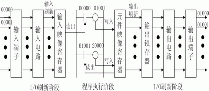
循环扫描工作过程:(1)公共处理(硬件检查、异常报警);(2)程序执行;(3)扫描周期计算处理;(4)I/O刷新;(5)外设端口服务。
信号传递过程:a. I/O刷新阶段---CPU从输入电路的输出端读出各路状态,并将其写入输入映像寄存器; b.程序执行阶段---CPU从输入映像寄存器和元件映像寄存器中读出各继电器的状态,并根据此状态执行用户程序,执行结果再写入元件映像寄存器中;
c.紧接着的下一个I/O刷新阶段---将输出映像寄存器的状态写入输出锁存电路,再经输出电路传递到输出端子,从而控制外接器件动作。
PLC的系统组成
CPM1A的基本组成
CPM1A继电器区及数据区
CPM1A功能简介
CPM2A简介
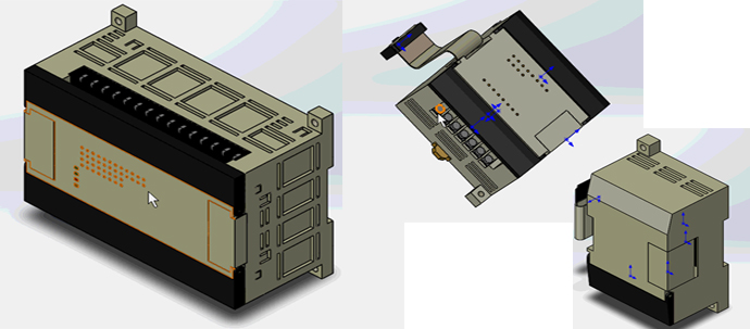
CPM1A的基本组成
- 主机
- 性能指标
- I/O扩展单元
- 编程工具
- 特殊功能单元
CPM1A继电器区及数据区
- 内部继电器区(IR)
- 特殊辅助继电器区(SR)
- 暂存继电器区(TR)
- 保持继电器区(HR)
- 辅助记忆继电器区(AR)
- 链接继电器区(LR)
- 定时器/计数器区(TC)
- 数据存储区(DM)
CPM1A功能简介
- 丰富的指令系统
模拟量设定功能
*输入时间常数设定功能
高速计数器功能
*外部输入中断功能
间隔定时器中断功能
*快速响应输入功能
*脉冲输出功能
高性能的快闪内存
较强的通信功能
CPM2A简介
- CPM2A主机及扩展单元
- CPM2A功能简介
本章作业
1、
2、
3、
提交时间